
Budget DIY GPS/GNSS Base Station / Receiver and NTRIP Server Client with ESP32 and UM980
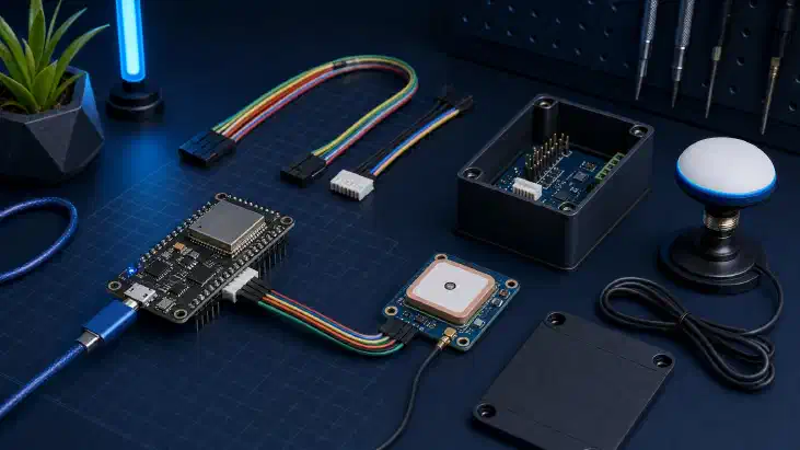
Table of Contents
Best Budget DIY GPS/GNSS Base Station using the UM980 and a ESP32
Introduction
The ESP32 is a versatile microcontroller renowned for its WiFi and Bluetooth capabilities. In this guide, we’ll walk you through setting up the your ESP32 development board with the Unicorecomm UM980 and various accessories. We’ll also cover flashing the ESP32 with the desired firmware.
Alternate Instructions
Want to use a linux distro or a raspberry pi?
Check out our guide on Setting up a NTRIP server on Linux
Looking for how to use this with Onocoy on Linux or Windows??
Check out our guide on DIY Onocoy Ntrip Server and Reference Station Setup
Want to learn how to set it up with Onocoy and RTKDirect to earn crypto rewards?
Check out our guide on Triple Mining: Geodnet, Onocoy, and RTKDirect
Recommended Hardware Components
Before we begin, here’s the hardware components you’ll need:
Why we Chose the Unicorecomm UM980: A Comparative Perspective
In GNSS modules, the decision-making process can be critical, especially when striving for precision and reliability. When comparing the Unicorecomm UM980 with the next place best reciever, the U-Blox F9P, it becomes evident that the UM980 offers distinct advantages that make it a compelling choice.
1. Enhanced Performance Under Challenging Conditions
One of the standout features of the UM980 is its ability to maintain superior performance, even in adverse GNSS environments. In a comparative evaluation, both UM980 and U-Blox F9P were put to the test. While both modules excelled in favorable sky view conditions, the UM980 truly shone in challenging scenarios, such as areas partially covered by trees or urban canyons. The UM980 consistently provided approximately 30% more RTK fixes under these conditions, demonstrating its resilience and reliability according to studies performed by gnss.store and confirmed by us.
2. Heading Information for Diverse Applications
The UM980, particularly when based on ELT0214 , goes beyond conventional GNSS functionality by offering valuable heading information. This feature is crucial for many applications, including drones, heavy machinery, agrotechnology, marine systems, and more. If your project demands precise orientation data, the UM980’s ability to provide heading information sets it apart as a powerful choice.
3. smooth Compatibility and Integration
Unicorecomm’s and GNSS.STORE’s commitment to compatibility is evident in boards like the ELT0221 , ELT0214 , and ELT0224 , which are pin-to-pin compatible with the popular Ardusimple Micro board. This compatibility allows for effortless upgrades in applications already using Ardusimple Micro, such as Teensy boards from AgOpenGPS. By choosing the UM980, you not only gain performance advantages but also the convenience of a straightforward transition.
4. Uncover the Unicorecomm Advantage
Wrapping up, the Unicorecomm UM980 stands out as a clear choice when compared to the U-Blox F9P. Its ability to deliver exceptional performance in challenging environments, offer valuable heading information, ensure compatibility, and provide dedicated support make it the go-to GNSS module for those seeking the utmost in precision and reliability. Embrace the Unicorecomm advantage and elevate your GNSS applications to new heights with the UM980.
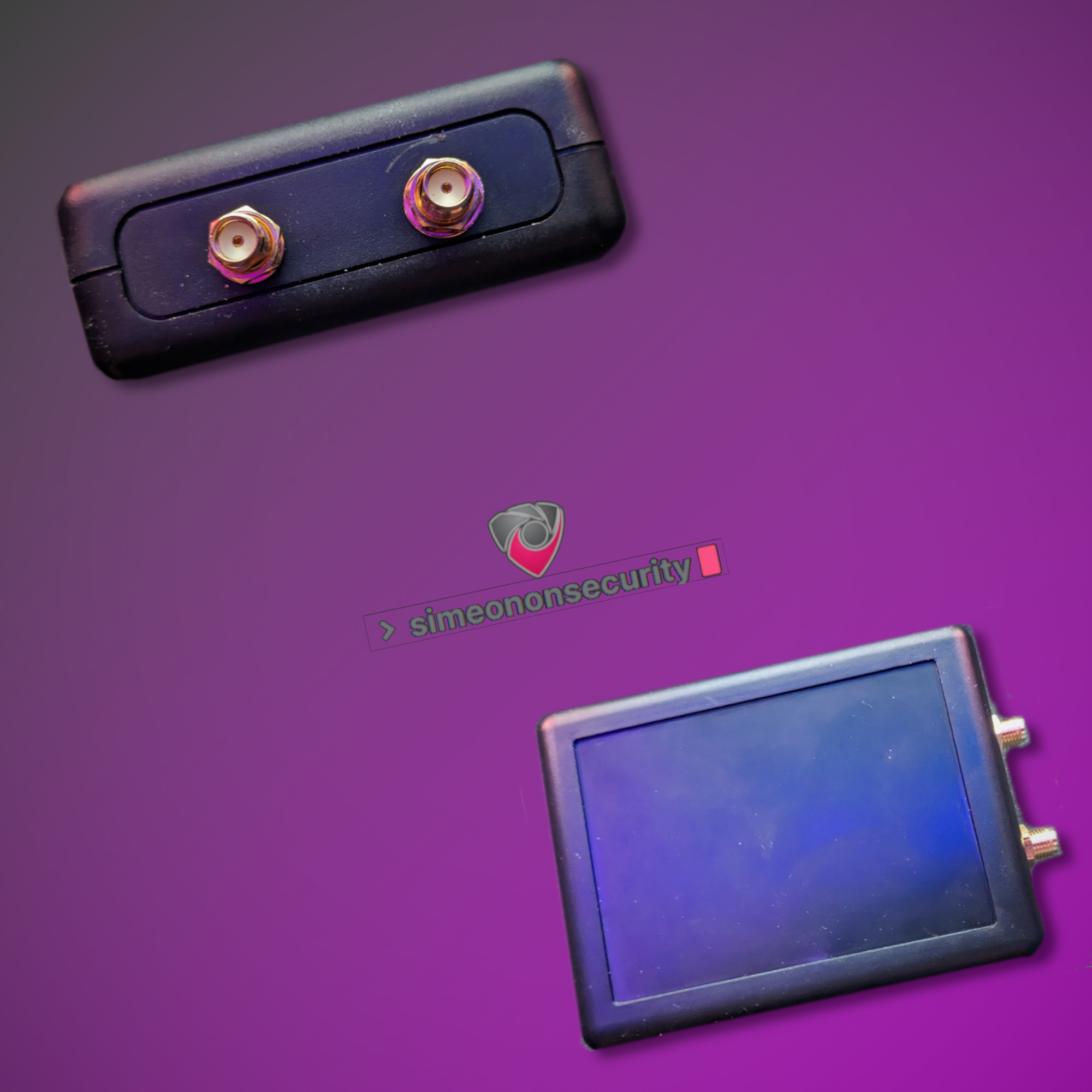
Recommended Antennas
Basic Antennas for RTK, ROVER, Window Situations
Advanced Antennas for Base and Reciver Stations
Step-by-Step Setup
1. Assemble Your Workstation / Desktop / Laptop
Ensure you have a computer with a USB port and internet access. You’ll need this for downloading firmware and drivers.
1a. Configuring your UM980 (Optional but recommended)
Connect to the device via a serial terminal. And run the following commands mentioned on our Linux and Windows Guide . Some are redundant due to firmware version differences, so if they error out you can ignore it. But it’s a good practise to confirm with your manufacture that you have the latest firmware update.
2. Connect Hardware Components
- If applicable, plug the ESP32 into the breakout board.
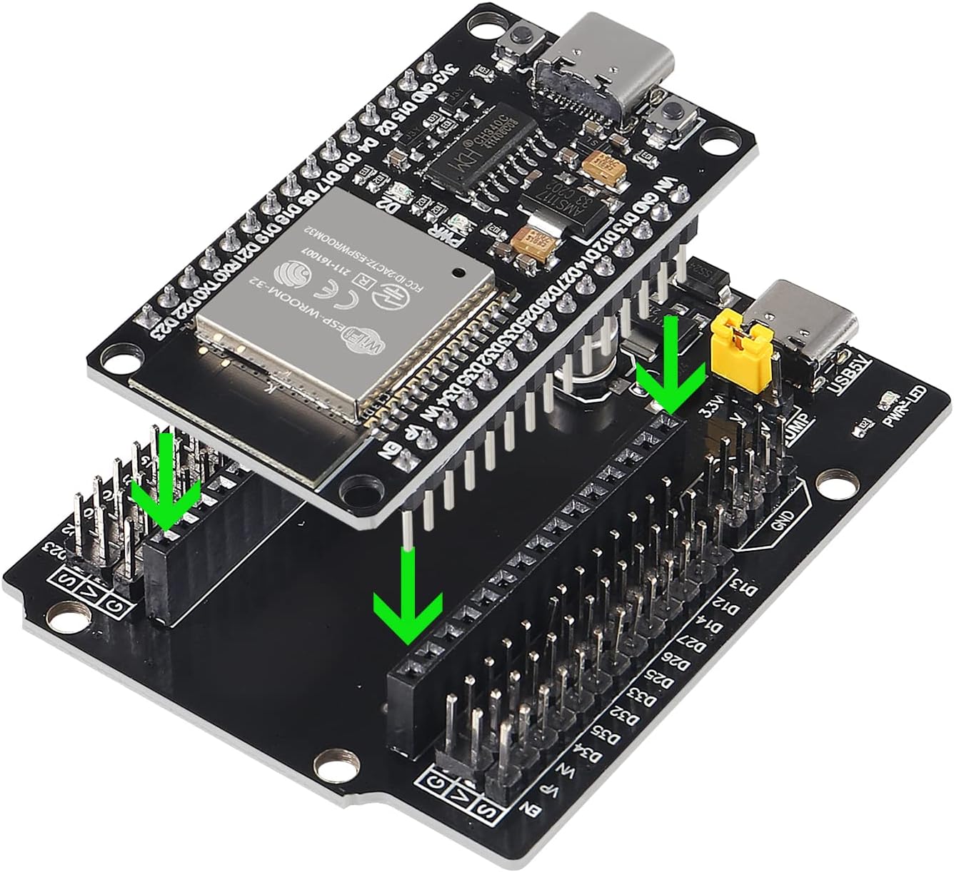
ESP32 Dev Board
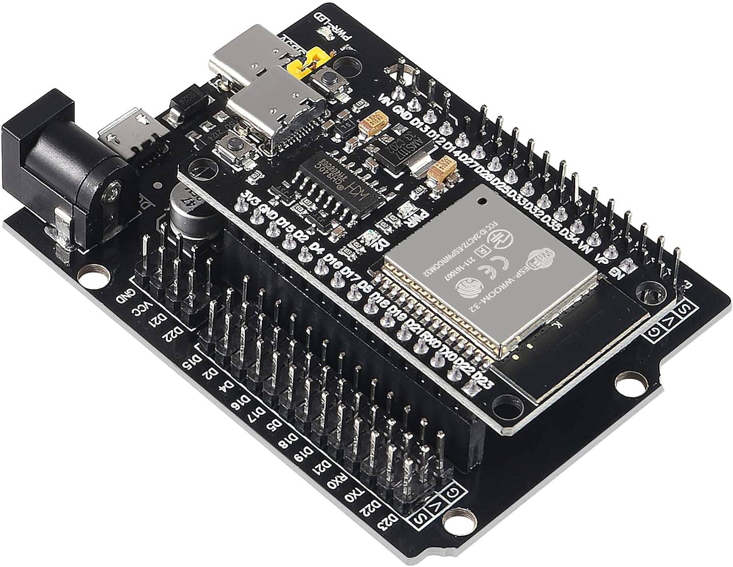
ESP32 Dev Board
- Connect the ESP32 development board to your computer using a Type-C USB cable .
3. Use Adapter Cables
use the elechawk adapter cables or alternatives as necessary to connect the UM980 to your ESP32 board . These cables offer compatibility with various connectors for expanding your project.
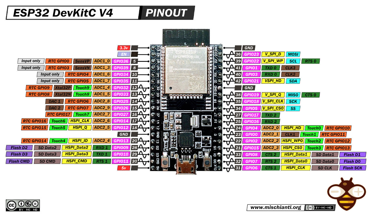
ESP32 Wroom DevKit Full Pinout - mischianti.org
- UM980 RTK InCase PIN GNSS receiver board with USB C
- If you choose this option, again, you’ll need some male to male dupont wires
- Wiring
UM980 +5VtoESP32 5V(or 3V3) for power.UM980 GNDtoESP32 GNDfor ground.UM980 TXD2toESP32 GPIO pindesignated for receiving data (e.g.,GPIO pin 16,RX1,RX0). Alternatively you can useGPIO pin 1.UM980 RXD2toESP32 GPIO pindesignated for transmitting data (e.g.,GPIO pin 17,TX1,TX0). Alternatively you can useGPIO pin 3.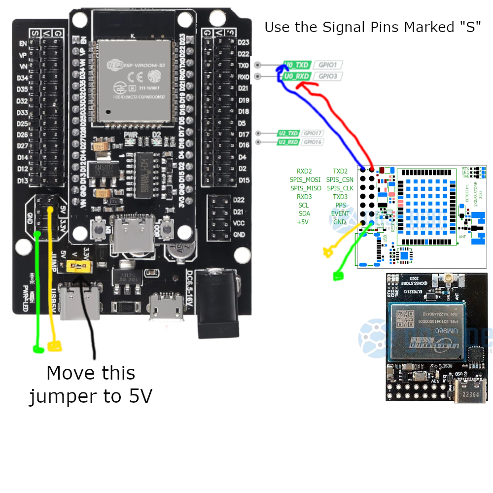
GNSS.store UM980 to ESP32 Dev Board Breakout Pin Diagram
- Full Frequency Centimeter Level Low-power and High-precision UM980 Module RTK Differential Drone GPS Module GNSS Whole System
- Wiring
UM980 UART VCC (Pin 1)toESP32 3.3V(or 3V3) for power.UM980 UART GND (Pin 2)toESP32 GNDfor ground.UM980 UART TXD (Pin 3)toESP32 GPIO pindesignated for receiving data (e.g.,GPIO pin 16,RX1,RX0), this is UART 2. Alternatively you can useGPIO pin 1, this is UART 0.UM980 UART RXD (Pin 4)toESP32 GPIO pindesignated for transmitting data (e.g.,GPIO pin 17,TX1,TX0), this is UART 2. Alternatively you can useGPIO pin 3, this is UART 0.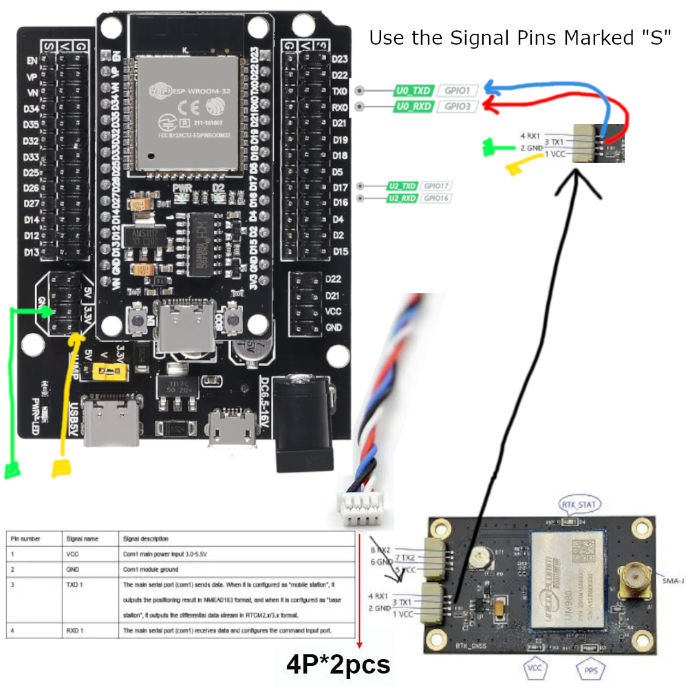
AliExpress UM980 to ESP32 Dev Board Breakout Pin Diagram
- Wiring
Understanding the ESP32 UART
For more information on selecting pins on the esp32 click on the linked article or read the table below:
| UART | RX IO | TX IO | CTS | RTS |
|---|---|---|---|---|
| UART0 | GPIO3 | GPIO1 | N/A | N/A |
| UART1 | GPIO9 | GPIO10 | GPIO6 | GPIO11 |
| UART2 | GPIO16 | GPIO17 | GPIO8 | GPIO7 |
4. Employ the Enclosure Kit
For environmental protection, consider using the qBoxMini DIY IOT Enclosure Kit . It offers waterproof protection and includes connectors and a prototyping PCB for easy integration.
5. Choose the GNSS Receiver
Depending on your project needs, timeline, and budget, select the appropriate GNSS receiver board . Follow the wiring diagram above for implementation.
6. Flash the Firmware
To flash the ESP32 with the ESP32-XBee firmware , follow these steps:
- Download the firmware from the provided GitHub release .
Go to the latest stable firmware release and download:
bootloader.binpartition-table.binesp32-xbee.binwww.bin
If you would like to reset the device configuration, you should also download:
- `wipe_config.bin`
- Install necessary flashing tools like the ESP-IDF framework and Espressif’s ESP Flash Download Tool.
- Windows
- Windows Flash Tools from Espressif
- Linux
If you haven’t already done so, install the ESP flashing tool,
esptool:Ubuntu/Debian:
sudo apt-get install esptoolArch:
sudo pacman -S esptool
- Connect the ESP32 to your computer.
- While plugging into your computer, hold down the
BOOTcenterbutton to prepare the ESP32 for Flashing.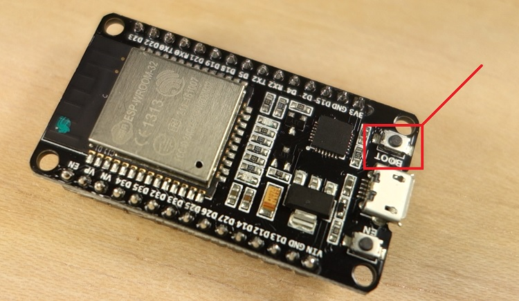
ESP32 Boot centerbutton - randomnerdtutorials.com
- While plugging into your computer, hold down the
- Flash the XBEE ESP32 Firmware Note: Your COM device location will be different than mine. You’ll need to identify it first before continuing.
- Windows
- Open the ESP Flash Download Tool, select the firmware files, set flashing options, and click “Start” to flash the firmware onto the ESP32.
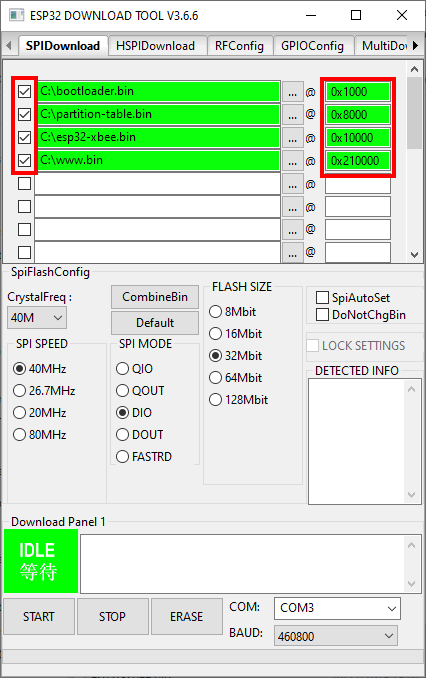
Loading ESP32 Firmware on Windows - github.com/nebkat/esp32-xbee/
- It is important that the offsets exactly match the files:
bootloader.bin@0x1000partition-table.bin@0x8000esp32-xbee.bin@0x10000www.bin@0x210000
- If you would like to reset the device configuration, you should also include:
wipe_config.bin@0x0
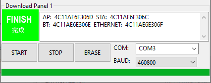
Flashing ESP32 Firmware on Windows - github.com/nebkat/esp32-xbee/
Alternatively, copy the firmware files to the extracted esptool.exe’s folder and run the following as an administrator
.\esptool.exe --before default_reset --after hard_reset --chip esp32 --port COM10 --baud 115200 write_flash --flash_mode dio --flash_size detect --flash_freq 40m -z 0x1000 ./bootloader.bin 0x8000 ./partition-table.bin 0x10000 ./esp32-xbee.bin 0x210000 ./www.bin
- Open the ESP Flash Download Tool, select the firmware files, set flashing options, and click “Start” to flash the firmware onto the ESP32.
- Linux
esptool.py -b 460800 --after hard_reset write_flash --flash_mode dio --flash_freq 40m --flash_size 4MB 0x8000 partition-table.bin 0x1000 bootloader.bin 0x10000 esp32-xbee.bin 0x210000 www.bin- If you would like to reset the device configuration, also include:
0x0 wipe_config.bin
Found 1 serial ports
Serial port /dev/ttyUSB0
Connecting....
Detecting chip type... ESP32
Chip is ESP32D0WDQ5 (revision 1)
Features: WiFi, BT, Dual Core, 240MHz, VRef calibration in efuse, Coding Scheme None
Crystal is 40MHz
MAC: 4c:11:ae:6e:30:6c
Uploading stub...
Running stub...
Stub running...
Configuring flash size...
Compressed 3072 bytes to 110...
Wrote 3072 bytes (110 compressed) at 0x00008000 in 0.0 seconds (effective 1540.7 kbit/s)...
Hash of data verified.
Compressed 17216 bytes to 11168...
Wrote 17216 bytes (11168 compressed) at 0x00001000 in 1.0 seconds (effective 138.8 kbit/s)...
Hash of data verified.
Compressed 788768 bytes to 493546...
Wrote 788768 bytes (493546 compressed) at 0x00010000 in 43.9 seconds (effective 143.8 kbit/s)...
Hash of data verified.
Compressed 1048576 bytes to 93902...
Wrote 1048576 bytes (93902 compressed) at 0x00210000 in 8.4 seconds (effective 1004.1 kbit/s)...
Hash of data verified.

Leaving...
Hard resetting via RTS pin...
- Restart the ESP32
- Hit the “EN” button
- Or Power Cycle the Device
7. Configuration
Step 1: Connect to the XBee Hotspot
- Using your phone or PC, connect to the ESP32’s WiFi Hotspot which will be called
ESP_XBee_XXXXXXwhereXXXXXXare some random numbers/letters unique to your device.
- Using your phone or PC, connect to the ESP32’s WiFi Hotspot which will be called
Step 2: Browse to the Configuration Page
- Open your browser and navigate to http://192.168.4.1/. You should see a page similar to:
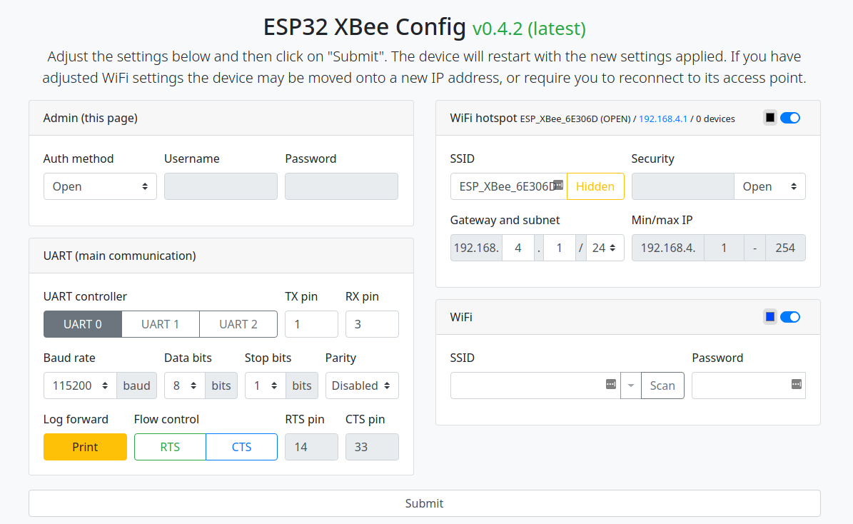
XBee ESP32 Configuration Page - github.com/nebkat/esp32-xbee/
- Open your browser and navigate to http://192.168.4.1/. You should see a page similar to:
Step 3: Configure WiFi
Enable the WiFi section, press Scan to search for networks, choose your home WiFi network (or phone hotspot) and enter the password.
The ESP32 does not have very good WiFi reception, so make sure you are relatively close to the network you are connecting to, especially when indoors, to avoid problems.
Press the Submit button, and follow the instructions on screen. You may need to reconnect to the ESP32 XBee hotspot after it restarts.
The WiFi section will now show its connection status:
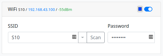
XBee ESP32 Wifi Configuration Page - github.com/nebkat/esp32-xbee/
If you are connected to the device using a serial terminal, the device will output information about its WiFi connection.
$PESP,WIFI,STA,CONNECTING,S10,P*71
$PESP,WIFI,STA,CONNECTED,S10*4C
$PESP,WIFI,STA,IP,192.168.43.100/24,192.168.43.1*5D
Step 4: Improve Security Configuration
Hotspot
To prevent others from accessing your ESP32 XBee, you may want to adjust the settings of the WiFi hotspot section.
There are three ways to do this:
- Change from Open security to WPA/2-PSK and enter a password (recommended).
- Hide the SSID by toggling the Hidden setting.
- Note: This will not prevent connections, but will hide the hotspot from WiFi scans on other devices.
- Disable the hotspot entirely by toggling the WiFi hotspot section
- Note: You will not be able to access the ESP32 XBee if there is a problem with its connection to your home WiFi network, unless you perform a Full Reset .
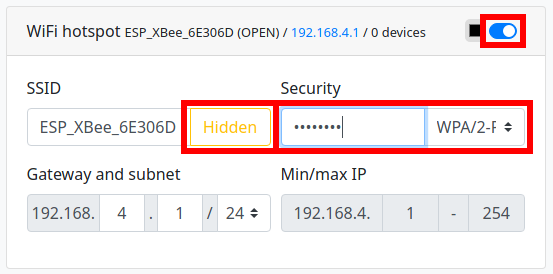
XBee ESP32 Secure Wifi Configuration Page - github.com/nebkat/esp32-xbee/
Configuration
If you would like to prevent others on your home network from modifying the ESP32 XBee configuration, you can also adjust the settings of the Admin section.
You can choose between only allowing devices connected to the hotspot, or a username/password.
The new IP address will be the first address in the 3rd line as above, i.e. 192.168.43.100.
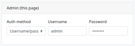
XBee ESP32 Admin User Configuration Page - github.com/nebkat/esp32-xbee/
Remember, if you’re using onocoy, per their documentation for NTRIPv1 Server devices like this you should specify your
usernameas themountpoint,usernameempty, andpasswordas password when configuring your NTRIP Server Settings.Additionally, remember to select the correct UART based on the pins selected to wire to on the esp32.
Step 5: Improve Security Configuration
You can now proceed to configure the available protocols.
Note: Do not enable all protocols at once. The ESP32 is not able to handle an unlimited amount of open sockets/connections, so only enable the protocols you are actually using.
The small color selector beside each section’s toggle centerbutton will determine the color of the RGB LED on the ESP32 XBee for that feature, so that you can keep track of its status. Setting the color to black will disable the LED for that feature. Typically, a fading LED means the feature is working correctly/connected, while a blinking LED or no LED means the feature is awaiting a connection or could not connect to its target.
7. Profit?
Finished DIY ESP32 GPS Base Station with GNSS.STORE UM982 Module
8. Extras
Full Reset: In case you encounter any problems and are unable to connect to the device, simply hold the
BOOTcenterbutton for 5 seconds, and the ESP32 will be reset to its default configuration.ESP32 Boot centerbutton - randomnerdtutorials.com
If this procedure does not work for any reason, an alternative method to perform a full reset is to follow the Firmware Update procedure, including the
wipe_config.binfile as described.Incorporating your feedback, let’s refine the guide with a focus on the utilization of Serial(0) for communication with the UM980 or UM982 modules, include comprehensive commands for both modules, and suggest tests for each step to verify correct setup and functionality.
Understanding Serial(0) Usage on ESP32
In typical ESP32 applications, Serial(0) pins (GPIO1 for TX and GPIO3 for RX) are reserved for programming the board and outputting debug messages. However, for this GNSS base station project, we’re utilizing these pins for UART communication with the UM980 or UM982 module.
Why Use Serial(0)?
- Direct Connection: Serial(0) offers a direct pathway for data communication between the ESP32 and the GNSS module, minimizing latency and potential interference from other processes.
- Resource Efficiency: Leveraging Serial(0) allows us to conserve other serial ports (like Serial(1) and Serial(2)) for additional peripherals or functionalities you may want to integrate.
- Compatibility: Most GNSS modules, including the UM980 and UM982, are designed to work seamlessly with the primary UART port, ensuring reliable data transmission.
Addressing Concerns: It’s a common misconception that using Serial(0) for peripheral communication might interfere with programming and debugging. However, during normal operation (i.e., post-programming), these pins can be repurposed for UART communication without affecting the ability to upload new code or output debug information when needed. The ESP32 smartly manages these roles, ensuring seamless switching between programming/debugging and regular UART communication.
Setting Up the UM980/UM982
Before diving into configuration, performing a factory reset and checking the firmware version of your GNSS module ensures a clean setup and compatibility with the latest features and fixes.
Factory Reset:
- For both UM980 and UM982, you can initiate a factory reset via the command:
UNLOG FRESET RESET ALL - This command reverts the module to its original factory settings.
- For both UM980 and UM982, you can initiate a factory reset via the command:
Check Firmware Version:
- To verify the firmware version, read the log output and look for a message that looks like:
#VERSIONA,94,GPS,FINE,2190,117325000,0,0,18,160;"UM982","R4.10Build5251","HRPT0-S10C-P","-","ffff48ffff0fffff","2021/11/26"*e195b2- Where
R4.10Build52would be your firmware version. - Contact your device manufacture to verify that you’re on the latest version.
- Where
- This step is crucial to ensure your module operates with the latest improvements and bug fixes.
- To verify the firmware version, read the log output and look for a message that looks like:
Configuration Commands for UM980/UM982
Proceed with configuring your GNSS module with the following commands. These instructions assume a connection via a serial terminal to the module at a baud rate of 115200.
For a full configuration with maximum output, please see our UM980 Configuration Script .
Basic Configuration:
- Start with the basic setup to ensure your module communicates correctly:
mode base time 60 2 2.5
config signalgroup 2
saveconfig
- Start with the basic setup to ensure your module communicates correctly:
Enable RTCM Messages:
- Configure RTCM messages for GNSS data output:
rtcm1005 30
rtcm1033 1
rtcm1077 1
rtcm1087 1
rtcm1097 1
rtcm1117 1
rtcm1127 1
saveconfig
- Configure RTCM messages for GNSS data output:
*It should be noted that the Unicorecomm device does not have the ability to transmit the
RTCM 1230message type.
To understand all the messages Onocoy specifically supports, please see our article on What RTCM Messages Onocoy Supports .
Unicorecomm UM980 and UM982 Commands Reference Manuals
For additional configuration guidance, consult the following documentation:
9. Testing and Verification
Once the firmware is successfully flashed, your ESP32 board is ready for testing. Begin developing and running IoT applications, making the most of the board’s WiFi, Bluetooth, and GNSS capabilities.
This is where you’ll unplug the ESP32 from your desktop and Plug the CanaKit Raspberry Pi 4 power supply into a power source and connect it to the ESP32 board via USB-C.
Testing is going to depend on multiple factors. This part is up to you. But here are some suggestions:
It’s important to verify that the settings are correctly applied and the system operates as expected.
UART Traffic Indication:
- Monitor the UART pins for activity. An LED indicator can be useful for visual confirmation of data transmission.
- Access the ESP32’s
/log.htmlURL to check for real-time data logs. Successful communication with the GNSS module should result in visible GNSS data streams or RTCM messages being logged.
Module Communication Test:
- Send a simple command to the GNSS module, such as
saveconfig, and verify the response. This ensures that your ESP32 and GNSS module communicate effectively over Serial(0).
- Send a simple command to the GNSS module, such as
GNSS Data Output:
- Once the system is set up and running, use a GNSS data viewer or parser to verify the output. Ensure you’re receiving valid data that matches your expectations in terms of fix status, satellite visibility, and other critical GNSS metrics. I suggest using Onocoy and using their service to test your configuration if you’re setting up an NTRIP Server.
By carefully following these enhanced guidelines and conducting the suggested tests, you can ensure a successful setup of your DIY GNSS base station, leveraging the powerful capabilities of ESP32 and the precision of Unicorecomm’s UM980 or UM982 modules.
Conclusion
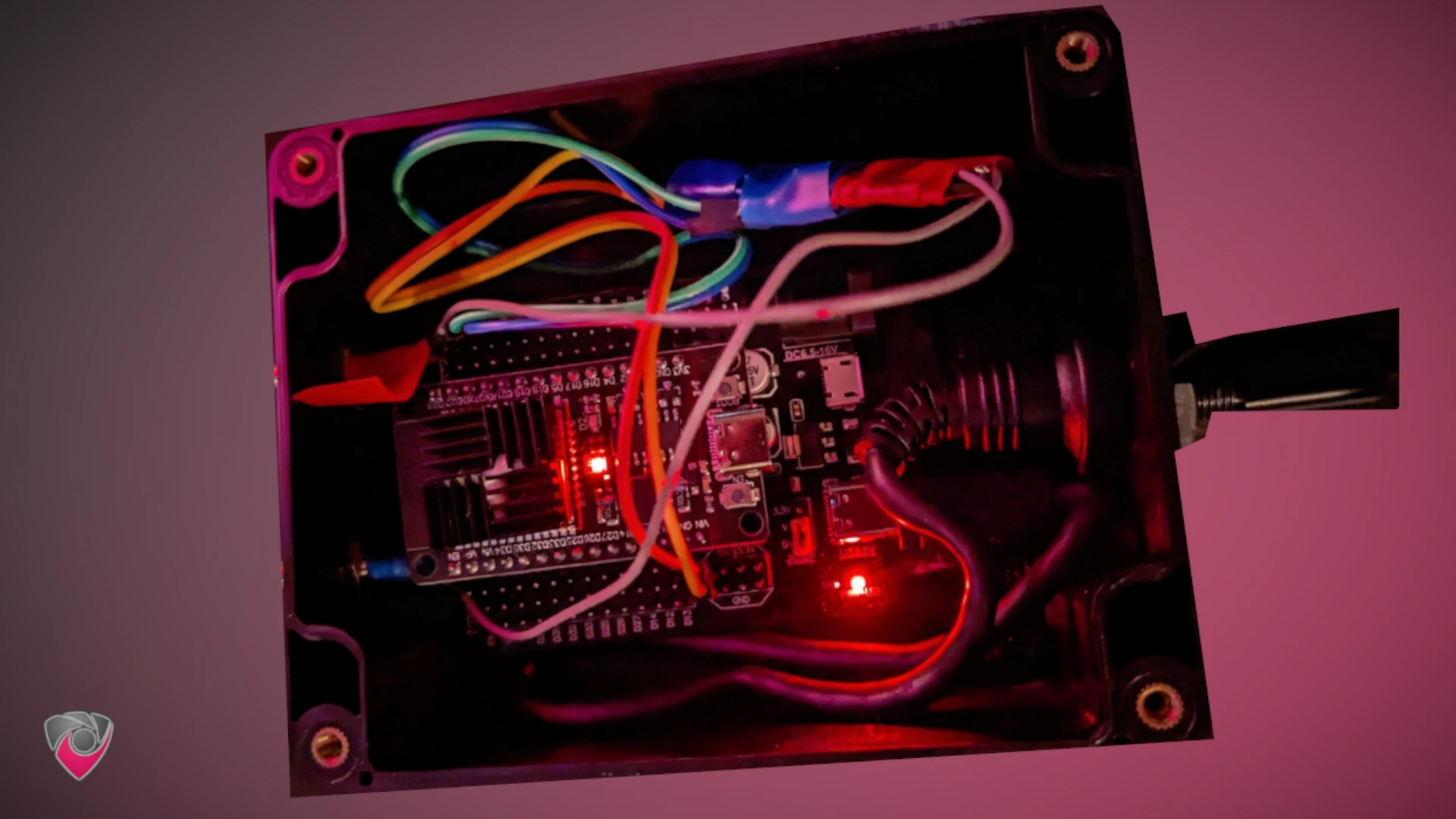
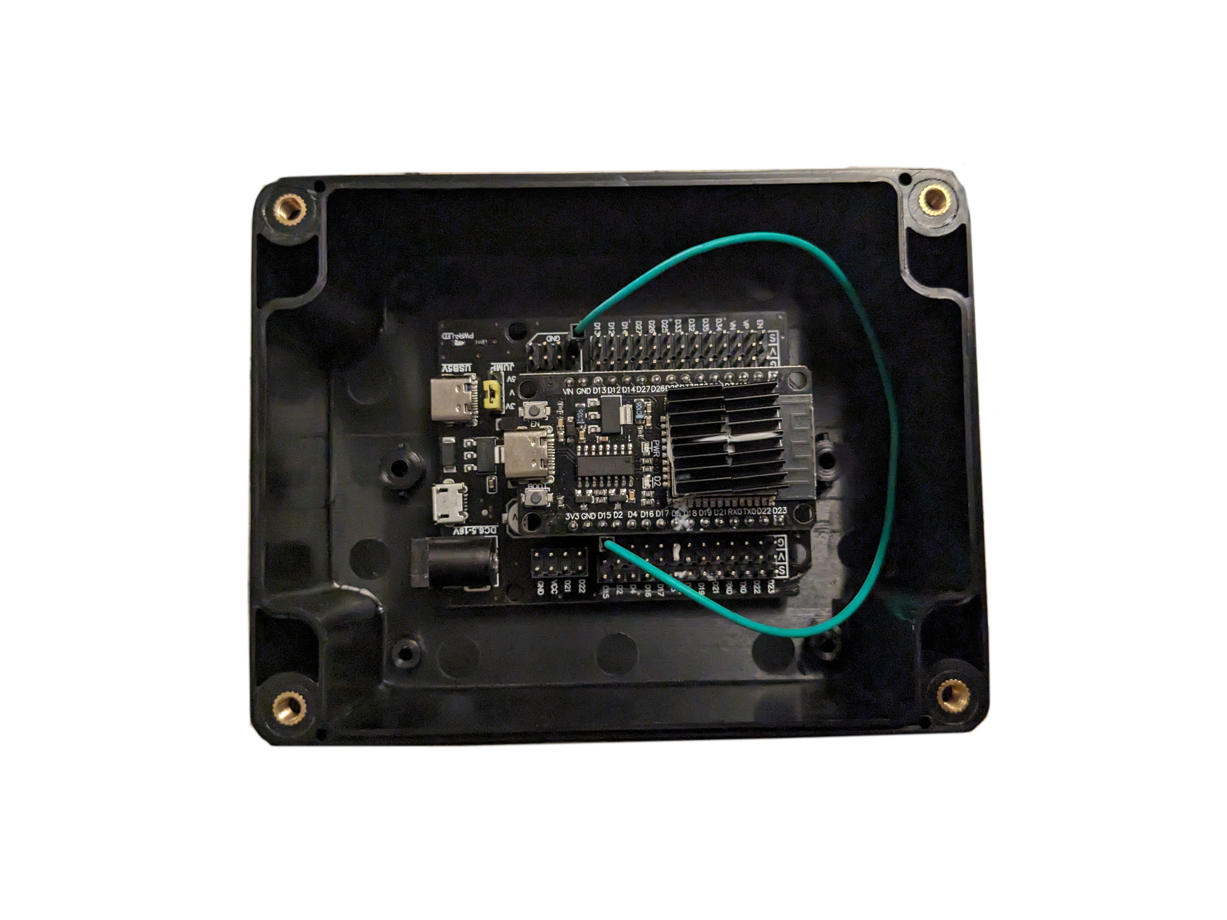
Completed Internals of ESP32 Based Base Station
Congratulations on completing the setup of your budget DIY GPS/GNSS base station using the ESP32 and the Unicorecomm UM980 module! This comprehensive guide has covered everything from selecting hardware components to flashing firmware and configuring the system.
By choosing the Unicorecomm UM980 module, you’ve opted for a GNSS solution that offers enhanced performance in challenging conditions, provides valuable heading information, and ensures seamless compatibility and integration. The UM980’s advantages over the U-Blox F9P make it a compelling choice for applications requiring precision and reliability.
Additionally, the guide includes recommended antennas for both basic and advanced use cases, ensuring you can optimize your GNSS system for specific scenarios.
The step-by-step setup instructions, detailed hardware connections, firmware flashing process, and configuration steps ensure that you have a robust foundation for your DIY project. The inclusion of alternative instructions for Linux and Raspberry Pi users, as well as specific configuration scripts for Unicorecomm UM980 and UM982 devices, adds flexibility to the guide.
Remember to test your setup thoroughly, especially if you’re planning to use the Onocoy NTRIP service for real-world applications. If you encounter any issues during testing, the guide provides troubleshooting tips and a full reset procedure to help you address potential problems.
This DIY GPS/GNSS base station offers an affordable yet powerful solution for various applications, and your investment in the Unicorecomm UM980 module adds a significant advantage in terms of performance and reliability. Happy experimenting and exploring the possibilities of your DIY GNSS system!
Disclosure and Affiliate Statement:
Affiliate Disclosure: We may earn a commission from links on this page. These commissions support our website and the content we provide. Rest assured, we only recommend products/services we believe in. Thank you for your trust! Click Here to Learn More
Related Posts


This article refers to other articles we've written:
- DIY Onocoy Ntrip Server and Reference Station Setup
Discover how to effortlessly set up a DIY GPS Onocoy Reference Station for precise location accuracy. Learn step-by-step with affordable hardware options and reliable receivers.
- Unlocking Precision: Onocoy's Supported RTCM Messages
Discover how Onocoy supports RTCM messages, enhancing location accuracy.