
Plan and Test VLAN Segmentation for a Homelab
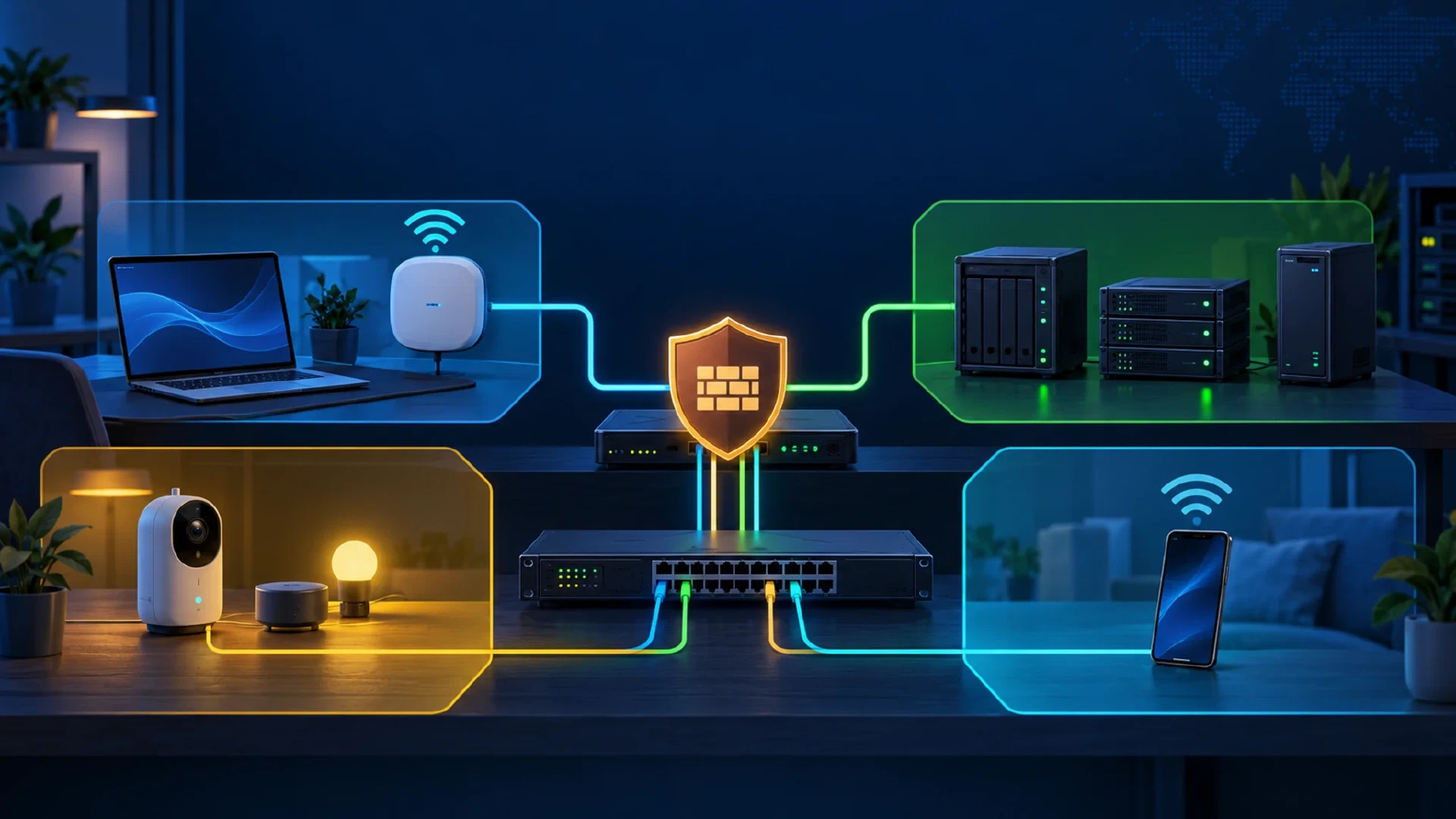
Table of Contents
A homelab often puts laptops, servers, cameras, and guest devices on one network. VLAN segmentation places those groups on separate networks. A router, firewall, or layer-3 switch routes traffic between them. Firewall rules or switch access control lists govern those routed flows. This guide helps you write the plan, make one change at a time, and test the result.
Key Takeaways
- Group by trust: Put management devices, servers, IoT devices, and guests in separate networks when their access needs differ.
- Write allowed paths: Record the source, destination, service, and reason for each cross-network connection.
- Configure both layers: Switch and access point VLAN settings place devices. Firewall rules or switch access control lists control routed traffic.
- Test both outcomes: Check an allowed connection and a denied connection from each relevant network.
Before You Begin
You need a router or firewall with VLAN interfaces, or a layer-3 switch that supports VLAN routing and access control lists. A managed switch carries the wired VLANs. You also need an access point with VLAN-backed wireless networks if you separate wireless clients. Keep a device on the current management network while you change the configuration. Save the router, switch, and access point settings first. The steps below use an illustrative plan, so adapt the addresses and ports to your equipment.
A VLAN interface is the gateway’s connection to one VLAN. The gateway might be a router, firewall, or layer-3 switch. A DHCP scope is the address range a DHCP service offers to devices there. A DHCP relay forwards address requests from a VLAN to a DHCP server on another network. Use a relay when the gateway does not serve addresses for that VLAN and the DHCP server sits elsewhere. Juniper’s DHCP relay guide describes this path. A wireless SSID is the network name clients join. If your equipment has no managed switch or VLAN-capable access point, start with its built-in guest network and verify its isolation before buying or changing hardware.
If you need the basic terms first, read subnets and VLANs . The site’s network segmentation guide covers the broader security concept. CISA describes separate home networks for guests and Internet of Things devices in its Federal Mobile Workplace Security guidance .
Warning: A VLAN change on the port carrying your management connection might lock you out. Keep physical access and a known recovery path until every network passes its tests.
Before moving a cable, export the configuration from each device and record the current management IP, switch port, VLAN setting, and administrator login. Leave one known-working management port and laptop on the original network. If a change cuts off access, reconnect the laptop to that port, restore the saved setting or configuration, and confirm the old gateway responds before trying again. If the switch has no reachable management path, use its documented console or local recovery procedure. Do not reset equipment until you know what its reset erases.
Inventory Devices and Flows
List each device, its current address, its owner, and the services it needs. Give every device a reason to reach another network. For example, a laptop might administer a server, while a camera might reach only a recorder and DNS server. A guest phone needs internet access but no server access.
| Device group | Example devices | Required access |
|---|---|---|
| Management | Admin laptop, switch and access point management | Router, switch, access point, server administration |
| Servers | Hypervisor, NAS, backup target | Updates, DNS, approved application traffic |
| IoT | Cameras, smart plugs, media devices | DNS, time service, specific controller or recorder |
| Guests | Visitor phones and laptops | Internet, DNS, no private subnets |
Write down exceptions before adding rules. Local discovery features such as casting often depend on multicast traffic that does not cross a routed boundary by default. Do not open all traffic between VLANs to repair one discovery problem. Identify the protocol and add the smallest supported exception.
Assign VLANs and Addresses
Give each group a VLAN ID and a separate IP subnet. This illustrative plan uses documentation addresses and assumes the router supplies DHCP and DNS. Do not copy the table into a live network without checking for address conflicts.
| Network | VLAN ID | Subnet | Example gateway |
|---|---|---|---|
| Management | 10 | 192.0.2.0/27 | 192.0.2.1 |
| Servers | 20 | 198.51.100.0/27 | 198.51.100.1 |
| IoT | 30 | 203.0.113.0/27 | 203.0.113.1 |
| Guests | 40 | 192.0.2.32/27 | 192.0.2.33 |
These reserved documentation ranges illustrate the layout only, as defined in RFC 5737 . Use private addresses from RFC 1918 for your actual lab, with a nonoverlapping subnet per VLAN. Record each real gateway, DHCP pool, DNS address, and device reservation in your plan.
Access ports carry one device network without a VLAN tag. Trunk ports carry selected tagged VLANs between the router, switch, and access point. Match the port’s VLAN ID and native or untagged setting at both ends. Netgate’s VLAN switch guide explains tagged trunk ports, untagged access ports, and port VLAN IDs. Avoid using the default VLAN 1 for management when your hardware permits a separate VLAN, as described in Netgate’s VLAN security guidance .
Native or untagged traffic on a trunk has no VLAN tag. The two ends must assign it to the same VLAN, or a device might land on the wrong network. Allow only the VLANs the link needs. Keep unused switch ports disabled or assigned to a restricted network. Netgate also advises against treating a VLAN as a complete security boundary when an attacker controls a switch port. Protect physical ports and device credentials as well as routed traffic.
Build a Traffic Matrix
A VLAN by itself separates broadcast domains. Inter-VLAN routing at the router or layer-3 switch still needs access rules. Decide which device routes between VLANs. If a layer-3 switch routes locally, traffic between its VLANs might never reach the router firewall. Apply equivalent access control lists on the switch or route through the firewall, then test at the actual enforcement point. Check the switch ACL’s direction and whether it tracks connection state. Many switch ACLs match packets separately in each direction, so an approved connection might need a narrow return-traffic rule. Cisco’s ACL guide describes interface direction and ordered packet matches. Use the device inventory to record the connections you intend to allow. The following entries are examples, not a universal rule set.
| Source | Destination | Service | Decision |
|---|---|---|---|
| Management | Server admin interface | TCP 443 | Allow for approved admin devices |
| Management | Router, switch, and access point admin interfaces | Their documented management ports | Allow for approved admin devices |
| IoT | Camera recorder | Recorder’s documented port | Allow only if needed |
| IoT | Approved DNS and time service | DNS and NTP | Allow only to the chosen services |
| IoT | Management subnet | Any | Deny |
| Guests | Private subnets | Any | Deny |
| Guests | DNS and internet | DNS, web traffic | Allow through approved resolver and gateway |
Include the router’s own services in the plan. A rule that blocks IoT access to other VLANs might still leave the router’s administrative interface reachable. Restrict management services to the management network. Start with only the required allow rules and a default deny for other routed traffic. Check existing broad allow rules before assuming the default denies anything. Netgate’s firewall best practices notes that a default pfSense LAN has an allow rule. If you use pfSense, its rule methodology explains that interface rules filter traffic entering that interface and that allowed connections create state for return traffic.
The sample table covers IPv4. If your network uses IPv6, assign an IPv6 prefix and policy to each VLAN, inspect router advertisements, and test allowed and denied IPv6 paths too. An IPv4 block does not prove IPv6 isolation. If you do not intend to route IPv6, check the router’s IPv6 settings and client addresses rather than assuming IPv6 is absent. Netgate documents IPv6 firewall behavior and router advertisements .
Configure One Network at a Time
- Choose the gateway for the VLAN. If the router or firewall routes it, create a VLAN interface there and assign its gateway address. If a layer-3 switch routes it, create the VLAN interface on that switch instead. Configure a DHCP scope on the gateway or a DHCP relay to your existing DHCP server. Confirm an approved DNS resolver is reachable. Netgate’s VLAN configuration guide lists the interface and service steps for a pfSense gateway.
- If the router is the VLAN gateway, add that VLAN to the router-to-switch trunk. If the layer-3 switch is the gateway, let the switch own that VLAN’s gateway address and route to the router or firewall over a separate transit network or routed uplink. Give the switch a default route toward the upstream router. Give the router a return route for each switch-owned VLAN through the switch. Check the router’s firewall policy and outbound NAT for those source subnets if they need internet access. Do not create the same gateway address or DHCP scope on both devices. Cisco’s inter-VLAN routing guide shows switch-owned VLAN gateways. Netgate documents return routes and outbound NAT for networks behind an internal router. Add the VLAN to the relevant switch-to-access-point trunk if wireless clients need the network.
- Assign one test access port or wireless SSID to the VLAN. Move a noncritical test device onto that port or SSID.
- Add the intended firewall rules or switch access control lists at the device that routes the VLAN. Verify that other routed traffic is denied. Check ACL direction and return traffic if the switch does not track state. Test access to each gateway and management interface, each local subnet, and IPv6 where present. Allow only the paths in your traffic matrix. Keep management access limited to the management network. Check rule order and remove or narrow existing broad allow rules only after the test management path works.
- Confirm the test device receives an address, gateway, and DNS server from the intended subnet. Then run the connection checks below before moving more devices.
Do not move the last management device until its replacement path works. Save the working configuration after each network passes. If DHCP, DNS, or management access fails, return the test device to the original port or SSID, restore the last switch or router change from the saved configuration, and retest the original network before proceeding.
Test Isolation and Access
Use a service you control and know is listening on the destination. From a Windows test device, replace the example address and port with a real server and run:
Test-NetConnection -ComputerName 198.51.100.10 -Port 443
The TcpTestSucceeded field reports whether a TCP connection completed. Microsoft’s
Test-NetConnection reference
documents the -ComputerName and -Port parameters. A failed connection alone does not prove a firewall rule worked. The service might be down, or the host firewall might reject traffic. Check the destination service and the network firewall log before drawing a conclusion.
Test from a device actually connected to each source VLAN. Record its source address, gateway, and DNS server before every test. Check an allowed connection to the intended service, a denied connection to an internal service outside the matrix, a DNS lookup through the intended resolver, and internet access where planned. For a switch-owned VLAN, check the switch’s default route, the router’s return route, and the path back from the destination if a permitted connection fails. Repeat the permitted and denied tests with IPv6 addresses if IPv6 is active. On pfSense, Status > System Logs > Firewall shows logged pass or block actions. Netgate’s firewall log guide explains the view. Compare the log’s source, destination, port, and rule to your test. If the test unexpectedly succeeds, inspect broad allow rules and existing state entries. Start a new connection after changing rules, since an established connection might keep working through its existing state.
For a DNS check on Windows, run nslookup example.com and compare the listed server with your planned resolver. Then try a lookup from a guest or IoT client where DNS is restricted. A successful lookup alone does not prove the client used the chosen resolver, so check the reported server and a firewall log or resolver log. Test direct access to the router’s management address from an IoT or guest device as a separate denied case.
Devices on the same VLAN might exchange traffic without passing through the router firewall. Test local client isolation separately if your access point offers it, and use host firewalls on servers. Cross-VLAN firewall tests do not prove same-VLAN isolation.
Expected Result: Each device receives an address from its planned subnet. Allowed services work. Denied attempts match a firewall block or a documented equivalent control.
Troubleshooting
- No address: Check the access port or SSID VLAN, trunk tags, DHCP scope, and gateway interface.
- Address works, DNS fails: Check the resolver address, router service binding, and firewall rule for DNS traffic.
- One device reaches another VLAN unexpectedly: Check router rules, broad allow rules, and whether both devices still share an untagged network.
- No firewall log for routed traffic: Check whether a layer-3 switch or alternate gateway routed the connection before it reached the firewall.
- Switch-owned VLAN reaches local networks but not the internet: Check the switch default route, router return routes, firewall policy, and outbound NAT for the VLAN subnet.
- IPv4 is blocked but the connection works: Check IPv6 addresses, router advertisements, IPv6 rules, and existing state entries.
- A denied test times out without a firewall log: Confirm the destination service is listening. Then inspect routing and logging settings. Netgate’s firewall troubleshooting guide describes the log and state checks.
- Casting or discovery stops: Identify the discovery protocol and controller path before adding a narrow exception.
Next Steps
Keep the device inventory and traffic matrix with your network diagram. Review the rules when you add a server or IoT device. Repeat one allowed and one denied connection test after each relevant network change. For the broader design principles, return to network segmentation .

Related Posts